High pressure float control valves in industrial refrigeration
Components
High pressure float control valves
High pressure float control valves in industrial refrigeration

This description is based on high-pressure floats from TH-Witt.
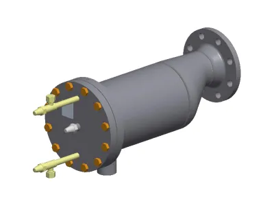
The high-pressure float regulator relieves all refrigerant on the high-pressure side on the low-pressure side, but without letting gas through. This simple mechanical method enables extremely energy-saving operation
Contents
Product Ad
Image

flangable highside float regulator
Jobs
Mounting
Mechanic/Welder (m/f/d) at GEA
We are looking for three mechanics/welders (m/f/d) at our Berlin location.
Image

GEA Refrigeration Germany GmbH
Berlin, Germany
Fulltime
Project management refrigeration technology
Commercial Employee Order Processing in Engineering (m/f/d)
To strengthen our team, we are looking for a commercial employee to handle engineering projects as soon as possible.
Image

MTA Deutschland GmbH
Nettetal, Germany
Fitter refrigeration technology
MTA Refrigeration Technician (m/f/d) in Customer Service for Baden-Württemberg
To strengthen our team for the Stuttgart region, we are looking for you as a Refrigeration Technician (m/f/d) for our customer service.
Image

MTA Deutschland GmbH
Nettetal, Germany
Fulltime
Get in Touch with the Author
If you have any questions or would like additional information, the author of this article is happy to assist you. Simply use the options below to get in touch directly.
Related Products
Image

flangable highside float regulator
Image

The simple and cost-efficient solution for refrigerant expansion.
Image

HFI is a high pressure float valve with internal liquid level control
Image

For industrial refrigeration applications. Featuring a 52 bar (754 psi) pressure rating and plated steel construction, these valves offer superior performance
Related Articles
Understanding Shut-Off and Control Valves: Essential Insights
When dealing with shut-off and control valves, it’s crucial to understand their operation and maintenance to ensure optimal performance and longevity.
What to Consider with Check Valves
The design is generally determined by the mass flow rate and not by the pipe diameter.
The refrigerant condenser
In the refrigeration cycle, the refrigerant releases its heat in the condenser. Different designs and systems are used in everyday life.
Sight glasses in refrigeration systems
Sight glasses provide important information on the condition of refrigeration and air conditioning systems.
Precise media temperature control
Precision refrigeration and air conditioning are essential for many applications
4-way reversing valves
Structure, function, assembly and use of 4-way reversing valves
Compressors for direct current
Compressor technology for mobile refrigeration technology and mobile cool boxes
Infinitely variable compressor capacity control
The combination of compressor and frequency converter for stepless speed control
mechanical cooling water regulator
Cooling water regulators are valves specially designed for water-cooled condensing units

