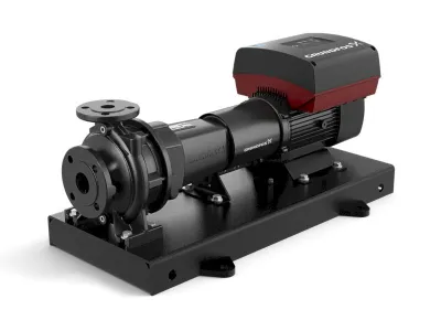
mechanical cooling water regulator
Structure – pressure-guided water valves
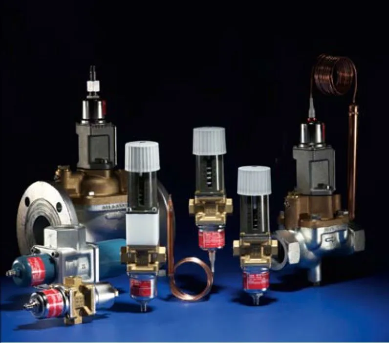
Water valves - pressure and temperature controlled
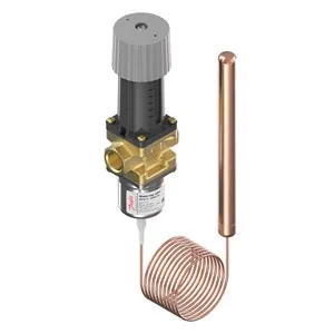
Cooling water regulators have two connections for the water circuit and one for the cooling circuit. The two water connections – at least those of the smaller devices with a pipe connection of up to 1 ½” – are designed as G inch internal threads, as has long been the standard in water technology. With connection sizes of 2, 3 or 4 inches, flange connections are standard, which are butt welded to the pipe side. The connection for the high-pressure side of the refrigeration system is designed as a 7/16 UNF flared nipple. This can be connected to the refrigeration system via a 6 mm copper pipe or a pre-assembled capillary pipe with the appropriate union nuts. With type "WVFX" up to size 25, there is a gray adjustment knob opposite the refrigerant side for adjusting the nominal condensing pressure. If this knob is turned in the "+" direction (counterclockwise), the setpoint and thus the desired condensation pressure (or the condensation temperature, respectively, because in the wet steam area of the condenser the pressure and temperature are constant to one another) increases. For example, if the condensation temperature with the refrigerant R404A is to be raised from 35 to 40 °C, the adjusting knob must be turned in the “+” direction, i.e. anti-clockwise. In contrast, turning in the "-" direction causes the condensation pressure or temperature to drop. For example, if the condensation temperature with the refrigerant R404A is to be raised from 35 to 40 °C, the adjusting knob must be turned in the “+” direction, i.e. anti-clockwise. In contrast, turning in the "-" direction causes the condensation pressure or temperature to drop. For example, if the condensation temperature with the refrigerant R404A is to be raised from 35 to 40 °C, the adjusting knob must be turned in the “+” direction, i.e. anti-clockwise. In contrast, turning in the "-" direction causes the condensation pressure or temperature to drop.
Structure - temperature-controlled water valves
The effect and setting of temperature-controlled water valves are exactly the same as their pressure-controlled relatives. The main difference is that a temperature is actually recorded as the actual value. For this purpose there is a remote sensor on temperature-controlled cooling water controllers (e.g. type "AVTA") that measures the current temperature. This means that even with an "ATVA" valve, it must be turned in the "+" direction (counterclockwise) in order to increase the setpoint, for example from 35 to 40 °C.
“WVFX” – “AVTA” setting
probe placement
Measuring the condensing pressure with a temperature-controlled device is not easy. While the outlet point of the control line for the refrigerant connection can be selected anywhere on the pressure side of the refrigeration system (hot gas or liquid side) with the "WVFX" pressure version, this is not possible with the "ATVA" temperature version. The value measured when the remote sensor is connected to the hot gas line does not correspond to the condensation temperature, but is significantly higher. This is because the refrigerant here is already fully gaseous and superheated. This point is therefore not suitable for attaching the "AVTA" sensor. The situation is similar with the liquid line, since the liquid refrigerant is already subcooled there. Thus the actual temperature is lower than the value which can be read on the high-pressure gauge as a pressure-temperature correspondence. The condenser outlet is more suitable, but the sensor should be installed in front of the collector. Apart from the problems described, there must also be good heat transfer from the refrigeration pipe to the sensor. Particular attention should be paid to this point if the sensor is mounted on a stainless steel pipe. Stainless steel is a poor conductor of heat. It is therefore possible that the current temperature is forwarded to the sensor and the "AVTA" cooling water controller with a slight delay. This leads to a more sluggish control characteristic and thus often to fluctuations in the condensing pressure. Attaching the sensor to the cooling water line itself is not normally advisable, because in general the sensor should always feel the medium to be cooled. If an "AVTA" is actually used to keep the cooling water temperature constant, then the following must be observed: In order to enable the valve to open again after it has closed, a bypass should be installed via the cooling water regulator. Otherwise there is a risk that the temperature-controlled cooling water controller will no longer open, since the temperature at the sensor point is low (no need to open) and warm water can no longer flow. a bypass should be installed via the cooling water regulator. Otherwise there is a risk that the temperature-controlled cooling water controller will no longer open, since the temperature at the sensor point is low (no need to open) and warm water can no longer flow. a bypass should be installed via the cooling water regulator. Otherwise there is a risk that the temperature-controlled cooling water controller will no longer open, since the temperature at the sensor point is low (no need to open) and warm water can no longer flow.
"AVTA" - temperature-controlled cooling water controller
temperature range
The control range is also decisive for the right choice of a temperature-controlled cooling water controller. There are "AVTA" and "WVTS" devices with a control range of 0 to 30 °C, 25 to 65 °C and 50 to 90 °C. At "AVTA" there is another special range with 10 to 80 °C. The "AVTA" / "WVTS" versions for ranges from 25 to 65 °C are therefore recommended for standard refrigeration systems with condensation temperatures between 30 and 55 °C. Theoretically, 10 to 80 °C is also conceivable, since the normal liquefaction range is also covered here. In practice, however, preference should be given to the 25/65 variant in this case, since this controller has a better control resolution due to its smaller temperature range. In the case of service, i.e. when replacing a temperature controller whose sensor is located in an immersion sleeve, the diameter of the sensors must also be taken into account. There are versions with a diameter of 9.5 and 18 mm. The explanations show that the pressure-controlled cooling water controller is generally more suitable for use in compression refrigeration systems than the temperature-controlled version. The latter is more recommended for special applications such as special refrigerants with high pressure.
Location of the valve in the system
Arrangement of the cooling water regulator
A frequently asked question relates to the placement of the chilled water regulator. It can be installed on the water side both before and after the condenser. In water systems, a coarse dirt filter should always be installed in front of the cooling water regulator. This serves to filter out larger foreign particles that are in the water system. Coarse dirt filters must be serviced regularly, with the maintenance intervals depending on the degree of contamination of the cooling water. As a rough guideline, six-monthly maintenance can be assumed. When using treated river water, as is often the case in large companies near a river, an even higher frequency of maintenance may be required. For the use of more aggressive media that would attack the housing of the standard cooling water regulator, there are also special versions of "WV-FX 10 - 25" in stainless steel. The addition of anti-freeze or the use of brine may be necessary during standstill phases in winter operation to prevent the vehicle from freezing
layout diagram
pressure drops
When dimensioning temperature and pressure-controlled cooling water controllers, the water volume flow and the performance of the cooling water controller play a role. This results in a certain pressure drop, which must always be taken into account when designing valves. With directly controlled cooling water controllers such as the pressure-controlled "WVFX" or the temperature-controlled "AVTA", the main focus is on avoiding excessive pressure drops, since both valve series can work stably even with the smallest pressure drops. In the case of servo-controlled cooling water controllers such as "WVS" (pressure) and "WVTS" (temperature), the minimum and maximum pressure drops must be observed. A "WV(T)S" requires a minimum water pressure drop of 0.3 bar in order to be able to work stably. If this value is not reached during the design, a smaller power rating must be selected. Otherwise the valve falls into unstable control mode. In pump operation, one should not allow excessive pressure drops. The reference value is a pressure drop well below the 1 bar mark.
Sectional drawing "WVFX" (pressure-guided)
The use of a line control valve is recommended to prevent the pump from working against a closed 2-way valve (the cooling water regulator). In such a case (valve closed), the balancing valve allows the water to flow back to the pump via a bypass. This ensures a continuous flow of water and at the same time prevents damage to the pump. If city water is actually present in front of the valve (e.g. with 4 bar water pressure) and then runs out freely, the valve can certainly be designed smaller. In practice, the pressure drop across the valve will always be 4 bar.
Pressure-guided water valve "WVFX" in high-pressure version
refrigerant suitability
In general, pressure-controlled cooling water controllers are suitable for all common HFC and HCFC refrigerants, as long as the control range at the permissible operating pressure harmonizes with the design criteria of the entire system. For example, a "WVFX 15" has a permissible operating pressure of 26.4 bar for the refrigerant connection and is therefore suitable for a system with the refrigerant R407C and a maximum operating pressure of 25 bar. With a set value of 40 °C (dew point temperature) on the high-pressure side of the refrigeration system, this corresponds to a gauge pressure of approx. 14 bar. "WVFX 15" is available with two different control ranges: 3.5 to 16 bar overpressure and 4 to 23 bar overpressure (gauge pressure). In the case described, the variant with 3.5 to 16 bar overpressure is suitable. In the same plant operated with 50 °C condensation, it would be the variant with 4 to 23 bar overpressure, since 50 °C condensing dew point temperature corresponds to about 19 bar operating pressure. However, the latter is more of a theoretical example, as systems with water-cooled condensers usually have lower condensation temperatures than air-cooled systems. For water-cooled systems, condensation temperatures between 30 and 40 °C are standard, even in summer. In air-cooled systems, this value is often 10 K higher. For particularly high pressures, there are also special versions of the "WVFX 10 - 25" with maximum permissible operating pressures of up to 45.2 bar and a working range of 15 to 29 bar overpressure. These devices are ideal for the refrigerants R410A or R744 (CO2) in subcritical operation. it would be the variant with 4 to 23 bar overpressure, since a condensation dew point temperature of 50 °C corresponds to around 19 bar operating pressure. However, the latter is more of a theoretical example, as systems with water-cooled condensers usually have lower condensation temperatures than air-cooled systems. For water-cooled systems, condensation temperatures between 30 and 40 °C are standard, even in summer. In air-cooled systems, this value is often 10 K higher. For particularly high pressures, there are also special versions of the "WVFX 10 - 25" with maximum permissible operating pressures of up to 45.2 bar and a working range of 15 to 29 bar overpressure. These devices are ideal for the refrigerants R410A or R744 (CO2) in subcritical operation. it would be the variant with 4 to 23 bar overpressure, since a condensation dew point temperature of 50 °C corresponds to around 19 bar operating pressure. However, the latter is more of a theoretical example, as systems with water-cooled condensers usually have lower condensation temperatures than air-cooled systems. For water-cooled systems, condensation temperatures between 30 and 40 °C are standard, even in summer. In air-cooled systems, this value is often 10 K higher. For particularly high pressures, there are also special versions of the "WVFX 10 - 25" with maximum permissible operating pressures of up to 45.2 bar and a working range of 15 to 29 bar overpressure. These devices are ideal for the refrigerants R410A or R744 (CO2) in subcritical operation.
Condenser Fan Speed Controller “XGE” – “RGE”