Components

4-way reversing valves

Structure, function, assembly and use of 4-way reversing valves

4-way reversing valves
 

construction

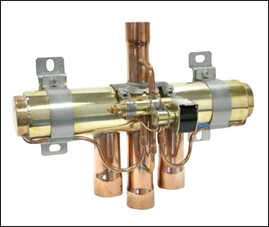
A 4-way reversing valve has four pipe connections. Three of these connections are placed on one side and one on the opposite side. The three copper pipe connections have a larger diameter than the single one on the opposite side. The middle of the three large connections is permanently on the suction side and the single, small connection is always on the pressure side. Since the other two can be either on the suction or on the pressure side - depending on how it is switched - they are designed in the dimension of the permanent suction line connection to take pressure drops into account. A 4-way valve also has a pilot solenoid valve with a coil, which can be used to change the refrigerant flow direction by energizing it.


function

For the following description, let's assume that the small (pressure) port is pointing up and the other three ports are pointing down. Here we see the small pilot solenoid valve with its coil. With a standard 4-way valve there are only two switching positions - no intermediate positions. In switching situation one, there is no voltage at the coil of the pilot solenoid valve.


3D view - coil energized


Functional diagram – coil energized


As a result, high pressure hot gas from the pilot line of the small port (permanent pressure side) is introduced into the slide mechanism chamber from the right. At the same time, the pressure on the left side of the slide chamber can be relieved via the permanent suction connection by outflow to the low-pressure side. This moves the slider to the left and opens the main paths from top to bottom right and far left to center. In switching situation two, the hot gas finds its way from the top to the left, while at the same time the suction gas can flow downwards from the right to the middle.


3D view - coil de-energized


Functional diagram – coil de-energized


This is achieved by energizing the coil of the pilot solenoid valve with supply voltage and injecting high pressure into the spool chamber from the left. The pressure on the right side can thus be relieved to the middle, lower main connection, which leads to the spool moving to the right.


Pressure drops and sizing

Pressure drops are fundamentally important for valve dimensioning. Excessive pressure drops generally have a negative effect on the energy efficiency of the refrigeration system, while pressure drops that are too small can disrupt the stable operating behavior of a servo-solenoid valve, for example. With 4-way valves, both points are less critical. Minimal pressure drops on the pressure or suction side are not a problem for 4-way reversing valves, since the spool mechanism responsible for switching the valve is actuated by the differential pressure between the high and low pressure side of the refrigeration system. This is useful because high and low pressure are present directly at this type of valve, which is not usually the case with other valves in a classic dry expansion refrigeration system. It is therefore not decisive for the functional reliability of the valve which pressure drop actually occurs, for example on the suction side between the refrigerant inlet and outlet. The issue of "excessively high pressure drops" is also hardly an issue with "Saginomiya" 4-way valves from Danfoss if the dimension of the suction line is used as the primary design criterion. If the 4-way valve is selected based on this pipe size, then in the vast majority of cases a valve with very moderate pressure drops is obtained. Of course, it is safer to consult the relevant performance tables to verify that the valve chosen is large enough. But in most cases this check is not really necessary. on the suction side between refrigerant inlet and outlet. The issue of "excessively high pressure drops" is also hardly an issue with "Saginomiya" 4-way valves from Danfoss if the dimension of the suction line is used as the primary design criterion. If the 4-way valve is selected based on this pipe size, then in the vast majority of cases a valve with very moderate pressure drops is obtained. Of course, it is safer to consult the relevant performance tables to verify that the valve chosen is large enough. But in most cases this check is not really necessary. on the suction side between refrigerant inlet and outlet. The issue of "excessively high pressure drops" is also hardly an issue with "Saginomiya" 4-way valves from Danfoss if the dimension of the suction line is used as the primary design criterion. If the 4-way valve is selected based on this pipe size, then in the vast majority of cases a valve with very moderate pressure drops is obtained. Of course, it is safer to consult the relevant performance tables to verify that the valve chosen is large enough. But in most cases this check is not really necessary. if the dimension of the suction line is used as the primary design criterion. If the 4-way valve is selected based on this pipe size, then in the vast majority of cases a valve with very moderate pressure drops is obtained. Of course, it is safer to consult the relevant performance tables to verify that the valve chosen is large enough. But in most cases this check is not really necessary. if the dimension of the suction line is used as the primary design criterion. If the 4-way valve is selected based on this pipe size, then in the vast majority of cases a valve with very moderate pressure drops is obtained. Of course, it is safer to consult the relevant performance tables to verify that the valve chosen is large enough. But in most cases this check is not really necessary.


arrangement

Such a valve is integrated into both the hot gas line and the suction line of a refrigeration system. The two permanent lines – i.e. the pipeline that is always the hot gas line, regardless of the switching of the valve, and the pipeline that is always the suction line – are particularly easy to assign for assembly. The hot gas line coming from the compressor is routed to the small connection of the 4-way valve. The suction line leading to the compressor is placed on the middle of the large connections. These two lines between valve and compressor do not change their function. In this context, it should be noted that the external pressure equalization of an expansion valve is always connected to the permanent suction line, i.e. to the line coming from the middle large connection of the 4-way valve must be connected. If this is not heeded, this external pressure equalization will be subjected to a pressure that is far too high, which initially does not allow the expansion valve to function (the valve is closed with all its might) and may even cause permanent damage to the expansion valve. The two outer large connections remain. These can now be temporarily on the high or low pressure side. 


Assembly

When installing the valve, the following must be observed with the standard soldering process (copper/copper solder joint, can be hard-soldered with, for example, "Silfos 15"): Real copper sockets, such as are usually found in this type of valve, must be used very easy to solder with copper lines. Due to the excellent thermal conductivity of copper and the precisely fitting slide mechanism, it is extremely important to limit the heat input on the valve during the soldering process as much as possible. For this purpose, a cooling, wet cloth should be wrapped around the valve during the soldering process. Once this hurdle has been overcome, the 4-way valve is a component that functions reliably throughout the entire service life of a refrigeration system.


use

4-way valves are used for circuit reversal of “one-to-one” refrigeration systems. With this reversal, the evaporator becomes the condenser and the condenser becomes the evaporator. This circuit is often used, for example, in air conditioning split devices that are supposed to cool in summer and heat in the transitional period. When heating, these devices then become air-to-air heat pumps. Another application can be the desire for efficient defrosting. With the circuit reversal of "one-to-one" systems, the evaporator, which has now become the condenser, can be defrosted from the inside. This means that the heat does not have to be carried to the ice in the evaporator by electric heaters in the evaporator package, but rather that hot gas is sent directly through the pipe system where ice has previously accumulated.


Contents
Service Ad
Energy consultants
Commercial refrigeration
Programmers
Expert refrigeration system
cold.world ENGINEERING

Köpenicker Straße 325
Haus 11
12555 Berlin
Germany

Jobs
Mounting
Mechanic/Welder (m/f/d) at GEA
We are looking for three mechanics/welders (m/f/d) at our Berlin location.
GEA Refrigeration Germany GmbH
Ber­lin, Ger­ma­ny
Fulltime
Project management refrigeration technology
Commercial Employee Order Processing in Engineering (m/f/d)
To strengthen our team, we are looking for a commercial employee to handle engineering projects as soon as possible.
MTA Deutschland GmbH
Net­te­tal, Ger­ma­ny
Fitter refrigeration technology
MTA Refrigeration Technician (m/f/d) in Customer Service for Baden-Württemberg
To strengthen our team for the Stuttgart region, we are looking for you as a Refrigeration Technician (m/f/d) for our customer service.
MTA Deutschland GmbH
Net­te­tal, Ger­ma­ny
Fulltime

Get in Touch with the Author

If you have any questions or would like additional information, the author of this article is happy to assist you. Simply use the options below to get in touch directly.

Related Products