Solenoid valves for refrigeration systems
Construction
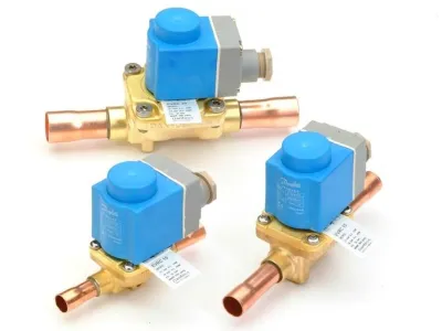
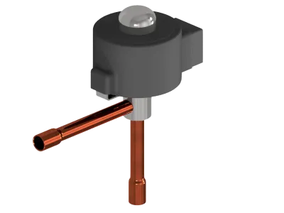
How is such a solenoid valve constructed? In general, a solenoid valve consists of a coil and a valve housing. The coil is mounted on an armature tube. In smaller, direct-acting valves, the moving armature opens and closes the valve by directly releasing or closing the valve seat. In order to achieve better internal tightness, the part of the armature that meets the valve seat is covered with a Teflon sealing pad. Examples of such direct-acting solenoid valves are the Danfoss types "EVR 2" and "3". In the case of servo-controlled solenoid valves, the armature movement takes place in the same way. However, instead of the entire valve seat, a servo bore is now closed or opened. In the case of servo valves with a diaphragm, this leads to a movement of the diaphragm via the differential pressures present at the valve, which then corresponds to the opening or closing process of the valve. The principle is the same for servo solenoid valves with pistons and without diaphragms. Here, too, the valve is opened and closed via the servo bore - but by means of a piston mechanism and not a diaphragm. a rough clustering according to performance variables makes sense. The solenoid valves with the smallest output, such as "EVR 2" and "3", are directly controlled. The two larger systems are then followed by the sizes "EVR 6" to "EVR 22", all of which are equipped with membranes and are servo-controlled. Finally, the solenoid valves "EVR 25" to "40" can be found for very high outputs with dry expansion. These are then servo-controlled piston valves. If these sizes are no longer sufficient, the main valves (e.g. Danfoss "ICS" or "PM valves") are simply made into a solenoid valve using a solenoid valve attachment (EVM). These combinations then leave little to be desired in terms of the size of the system.
A practical tip :
If you open a solenoid valve and find neither a membrane nor a piston in it, then it is usually a directly controlled valve. This will then also have smaller connections, such as 6, 8 or 10 mm.
SIZING
Why is it important for the practitioner to know whether he is dealing with a direct or servo-controlled solenoid valve? In fact, this point is crucial for the sizing of the valves. Direct acting solenoid valves do not require a minimum pressure drop to operate. For this reason, these valves have an extremely good partial load capability, which makes it possible to project a moderate pressure drop for the full load case (valves “EVR 2” and “EVR 3”). In the case of forced servo-controlled valves (e.g. types such as "EVRAT" or "EVRST" - the letter "T" stands for forced servo control) the same design criteria apply as for directly controlled valves. Again, there is no minimum pressure drop that needs to be taken into account. With servo-controlled valves ("EVR 6", "10", "15", "20", "22", "25", "32" and "40"), on the other hand, the minimum partial load case must also be considered in addition to the maximum pressure drop. At minimum partial load, the minimum pressure difference that the valve needs in order to be able to work stably must not be fallen below. This minimum pressure difference of the valve can be seen from the corresponding technical data sheets. Example: an "EVR 10" has a required minimum pressure drop of 0.05 bar. With 20 kW cooling capacity, R134a and -10 °C evaporation, i.e. normal cooling, and installation in the liquid line, the "EVR 10" would initially not be a bad choice, because a pressure drop of 0.06 bar at full load is more than 0.05 bar and is therefore in order. However, if, for example, two 10 kW compressors of the same size are connected together and press on this cooling circuit, then the minimum pressure drop is undershot when only one compressor is operated. Mathematically, there would then only be a pressure drop of 0.02 bar. Thus, in this case study, preference should be given to "EVR 6". With "eVR 6" the minimum pressure drop of the valve is also 0.05 bar. The full load pressure drop is 0.36 bar and the part load pressure drop is 0.09 bar. Both values are greater than 0.05 bar. Thus, the valve works stably in every assumed operating state. If, despite intensive efforts for full-load cooling performance, for which solenoid valves from size "EVR 6" would normally have to be used, no suitable valves can be found due to a partial load that is too low, a corresponding main valve can technically be used instead. Mathematically, there would then only be a pressure drop of 0.02 bar. Thus, in this case study, preference should be given to "EVR 6". With "eVR 6" the minimum pressure drop of the valve is also 0.05 bar. The full load pressure drop is 0.36 bar and the part load pressure drop is 0.09 bar. Both values are greater than 0.05 bar. Thus, the valve works stably in every assumed operating state. If, despite intensive efforts for full-load cooling performance, for which solenoid valves from size "EVR 6" would normally have to be used, no suitable valves can be found due to a partial load that is too low, a corresponding main valve can technically be used instead. Mathematically, there would then only be a pressure drop of 0.02 bar. Thus, in this case study, preference should be given to "EVR 6". With "eVR 6" the minimum pressure drop of the valve is also 0.05 bar. The full load pressure drop is 0.36 bar and the part load pressure drop is 0.09 bar. Both values are greater than 0.05 bar. Thus, the valve works stably in every assumed operating state. If, despite intensive efforts for full-load cooling performance, for which solenoid valves from size "EVR 6" would normally have to be used, no suitable valves can be found due to a partial load that is too low, a corresponding main valve can technically be used instead. With "eVR 6" the minimum pressure drop of the valve is also 0.05 bar. The full load pressure drop is 0.36 bar and the part load pressure drop is 0.09 bar. Both values are greater than 0.05 bar. Thus, the valve works stably in every assumed operating state. If, despite intensive efforts for full-load cooling performance, for which solenoid valves from size "EVR 6" would normally have to be used, no suitable valves can be found due to a partial load that is too low, a corresponding main valve can technically be used instead. With "eVR 6" the minimum pressure drop of the valve is also 0.05 bar. The full load pressure drop is 0.36 bar and the part load pressure drop is 0.09 bar. Both values are greater than 0.05 bar. Thus, the valve works stably in every assumed operating state. If, despite intensive efforts for full-load cooling performance, for which solenoid valves from size "EVR 6" would normally have to be used, no suitable valves can be found due to a partial load that is too low, a corresponding main valve can technically be used instead.
Practical tip:
Small main valves of the "PM" or "ICS" series with pilot valve "EVM" are very suitable for partial loads and can often still be used when the corresponding partial loads can no longer be operated with the standard "EVR" solenoid valves. The disadvantage of these valve combinations is the higher price compared to the standard "EVR". another solution for such partial load cases can be forced servo-controlled valves (minimum pressure drop 0 bar). These valves such as "EVRAT" and "EVRS T" were originally designed for ammonia, but can also be used for "copper refrigeration".
ARRANGEMENT
The main area of application for solenoid valves is the liquid line. An estimated 95% of all solenoid valves in refrigeration technology are installed there. Placing the solenoid valve close to the expansion valve is advisable, but not absolutely necessary. This minimizes the risk of accelerated liquids occurring. However, since this effect (it becomes noticeable through vibrating pipelines and knocking noises when opening the solenoid valve) is rather rare in commercial refrigeration systems, the solenoid valve can be arranged as desired if the structural conditions suggest it. The question of whether a solenoid valve should be mounted upstream or downstream of the dryer sight glass group is more of a "question of belief". If the solenoid valve is placed in front of the sight glass in the flow direction, in this way you can monitor the suction process if the system is switched to "pump down" or "pump out". However, this arrangement is not mandatory.
ASSEMBLY
Solenoid valves for "copper refrigeration" are equipped with either flared connections or soldered connections. The tube connections of the flared connections can be connected to the mounting tube in the classic way using a flare bell or using flared adapters. Flared adapters offer the advantage that this screw connection is then no longer considered a flared connection and therefore certain restrictions listed in the EN 378 standard no longer apply. In the event of service, it can also be exchanged without soldering. one disadvantage is that soldering still has to be carried out on both connection ends. In the case of soldered connections, the classic method is to braze directly on the valve. It is usually not necessary to disassemble the solenoid valve for this. Using a cooling wet rag is usually sufficient. "EVR" solenoid valves should be installed in a horizontal pipe section preferably with the coil (armature tube) facing up. Under difficult assembly conditions, the anchor tube may also be turned to the horizontal. (Pipe connections horizontal and towards the anchor tube looking away to the side). Intermediate positions between these two extreme positions are also conceivable.
APPLICATION
However, "EVR" solenoid valves for refrigerants cannot only be used in the liquid line. It can also be used in hot gas, condensate, suction and hot gas bypass lines. in hot gas, hot gas bypass line operation and in hot gas feed valves for hot gas defrosting, particular attention should be paid to the maximum permissible media temperatures of the solenoid valves. With the "EVR" this is 105 °C. In the case of solenoid valves for the suction line, the more interesting value is the minimum media temperature. This is at "EVR" -40 °C. It should be noted that even evaporating temperatures of -45 °C are not a problem as the refrigerant in the suction line is already overheated. This means that at least 7 k must be added to the evaporation temperature of -45 °C. With this calculated -38°C you are again fully within the range of application. If a hot gas bypass solenoid valve is to be installed in addition to a hot gas bypass regulator, an "EVR" can be selected with confidence. However, if this solenoid valve is also to take over control tasks and be clocked every minute, then a special solenoid valve type "EVRP" should be used for high clock rates.
MOPD
An interesting point about solenoid valves is the “MOPD”. "MOPD" means " maximum opening pressure differential".' and stands for the maximum opening differential pressure that can be withstood by the valve-spool combination in question. This "MOPD" depends significantly on the type of solenoid valve, but also on the coil used. For example, an "EVR 3" with a 10 W AC coil can hold 21 bar and with a 12 W AC coil 25 bar. This point is not a problem when used in the liquid line and in normal cooling operation. However, if suction is then drawn off by closing the solenoid valve and the system is switched off via the low pressure switch, the solenoid valve must maintain the full differential pressure between the high and low pressure sides. an example of this would be with normal refrigeration R134a -10 °C evaporating temperature = 1 bar gauge pressure (overpressure) and 45 °C condensation temperature = 10.5 bar. This means that the solenoid valve (10.5 – 1 =) must be able to hold 9.5 bar. This is usually possible without any problems. With R404 A or R507, these pressure values are usually higher. in these cases one should keep the “MOPD” issue in mind. As a practical tip, if in doubt, replace a 10 W standard coil with the "stronger" 12 W coil. This is not a big effort, never has negative effects and may help in a borderline case.
COIL
An important aspect of solenoid valves is the coil. The installation of the coil in the current “clip on” design is extremely easy. Simply attach the coil to the armature tube of the solenoid valve base and press once until it snaps into place - done. The spool is in one piece and closed at the top. It is important to check whether the O-ring at the lower end of the armature tube (at the transition from the armature tube to the housing) is fitted and undamaged. This O-ring is used to seal the coil against moisture (including humidity). From the outside, the coil body is diffusion-tight, moisture can only penetrate from the inside (from the armature tube). This internal moisture is the main enemy of solenoid valve coils. If you have older versions of these coils in front of you, then the seal at the upper end of the anchor tube must also be checked. These versions (designation "18Z" = older version, in contrast to "18F" = clip on) are initially open at the top and bottom and are fastened (screwed) and sealed with appropriate mounting material.
Practical tip:
If you find a burst spool where "plastic noses" have already formed on the outside, the reason for this is usually moisture that has penetrated the spool from the inside. If you can see brown spots of rust on the inside of the coil, then it can be assumed that the coil is not sufficiently sealed. When repairing, this point in particular should be taken into account (mount a new coil and seal it with the O-ring).
NC/NO
Solenoid valves are available in NC (“ normally closed” = normally closed ) and NO versions (“ normally open” = normally open).). The usual solenoid valves in the liquid line are designed as NC valves. This has the advantage that the valve is closed when the system is at a standstill and the solenoid valve coil is de-energized, which offers advantages in terms of avoiding refrigerant migration. For this reason, even a power failure of the energy supplier does not lead to any problems with the refrigeration system. The use of NO valves, on the other hand, can be particularly advisable if the valve should only be closed for a short time. Even if coils are not one of the main power guzzlers in a refrigeration system, quite a bit of energy costs can be saved over the years. With "EVR" solenoid valves, all performance sizes ("EVR 2 - 40") are available in version NC, but only "EVR 6 - 22" in NO.
Practical tip:
How can you tell whether it is an NO or NC valve if the type designation is no longer recognizable on the valve? At the top of the armature tube, each Solenoid Valve (“EVR”) has a circumferential groove that is used to attach the coil. This is the same for NC and NO. However, if there is another circumferential groove at the lower end (near the rest of the solenoid valve housing), then it is an NO valve. NC valves have only one groove in the armature tube.
Stephan Bachmann,
Danfoss Kältetechnik, Offenbach