Applications

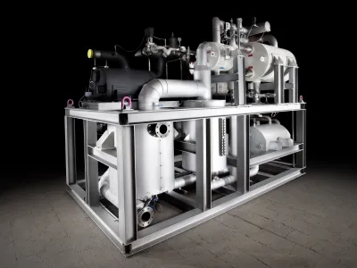
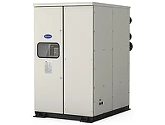
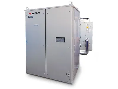
Ammonia / water absorption chiller

The ammonia / water absorption principle in refrigeration

The ammonia / water system

Ammonia is the refrigerant and water is the absorbent. On the left side of the bordered field in the picture is a circuit with an internal heat exchanger for condensate supercooling / steam overheating. It sends vaporized low-pressure refrigerant - in this case ammonia - into the system in the framed field and receives back under high pressure ammonia vapor. When the devices shown in the field are replaced by a compressor (and a desuperheater), the process becomes the normal compression refrigeration process.

Instead of mechanical energy, the absorption system mainly uses heat to reach an increase in pressure. Ammonia is extremely soluble in water and is thus constantly dissolved in the absorber. Since the process is exothermic, the absorber must be cooled. After the absorber, a pump increases the liquid pressure to the condensation pressure. At this higher pressure, ammonia vapor and liquid water are recovered. This is complicated by the fact that both ammonia and water are volatile substances. Distillation is therefore necessary. A chemical engineer would recognize the equipment as a distillation column with an expeller, a reflux condenser and an inlet / sump heat exchanger - a very common construction in the chemical industry.

In this way it is possible to obtain ammonia vapor with a purity of more than 99.5%. Because of the affinity of ammonia to water, it is virtually impossible (and not necessary) to recover pure water as the bottom product. The bottoms product - the poor solution - contains about 20-40% ammonia. After absorption, the rich solution contains 5-30% more ammonia, about 40-50%. Finally, the rich solution in the inlet preheater should be heated to the distillation temperature and the poor solution cooled to facilitate absorption.

All tasks in an ammonia absorption plant can be handled by PHEs. These range from nickel-brazed units in small home air conditioners to welded or cassette-welded PHEs in large industrial or commercial facilities. The thermal problems are almost the same everywhere and size independent. Most items are non-critical and, with the exception of certain features, can be treated as normal one- or two-phase heat exchangers.


The reflux condenser

The picture shows a reflux condenser. This liquefies a part of the steam and returns it as reflux into the column. A return is needed to provide liquid to the part above the inlet - the reinforcing column. The steam rises in the condenser and meets in countercurrent to the downwardly flowing condensate stream. This requires a condenser with a very low pressure loss. Here, a plate heat exchanger can be used, but only if the steam velocity / pressure loss is low, otherwise there is a risk of flooding the condenser.

A low pressure loss is almost automatically ensured if the condenser is designed with high heat recovery, ie only for a few degrees of temperature difference. If the condenser is designed for cooling water - which usually means a larger temperature difference - the number of plates will decrease and the pressure drop will increase, creating conditions for flooding.

It is difficult to specify exact design conditions. A calculated pressure loss of 0.05 - 0.1 kPa / m flow path, which corresponds to a flow of 20 kg / (m.h) of 20 bar ammonia vapor in a 2 mm channel, appears to be safe. It is also possible to operate the reflux condenser with downward flow of steam and condensate. However, this design is critical because a liquid column becomes necessary to overcome the pressure drop and force the condensate back into the column, or an additional pump must be used. Thermodynamically, this is less favorable than an upward current because it separates water and ammonia more effectively.


The Ammonia evaporator

He works like a normal, simple ammonia evaporator. However, in some cases, especially when a thermosyphon evaporator is used, the water content of the vaporized gas is lower than in the inflowing condensate. The water then accumulates in the evaporator and the evaporation temperature rises.

An additional evaporator is then necessary - similar to the oil evaporator in a Freon Thermosi phon (see Section 16 or 8. Oils and Refrigerants).

A DX evaporator is then a better choice, especially if it can be arranged so that all liquid droplets leaving the evaporator move directly to the absorber without encountering any pockets where they can settle. The best would be a liquid injection at the head of the NBPHE. But so far, all top liquid injection evaporator designs have clearly shown 25 to 30% lower performance. 

 Ammonia water absorption chiller

Picture 1: The ammonia / water absorption chiller process

The cold section:

1.   The condenser condenses the ammonia vapor.

2.   The liquid receiver compensates for fluctuations in the effective refrigerant charge.

3.   The internal heat exchanger undercuts the condensate with refrigerant vapor; increases process efficiency.

4.   The expansion valve: thermostatic DX valve.

5.   The evaporator is here a normal DX evaporator.

The absorption part:

6.   The absorber consists of two parts, the injection stage, where the cooled poor solution is sprayed into the ammonia vapor, and the remaining condenser. The ammonia dissolves easily in the poor solution, assisted by intense turbulence in the cooled, corrugated channels. The resulting rich solution leaves the absorber and enters:

7.   The pump that raises the pressure from the evaporation to the condensing pressure and feeds solution into:

8. The inlet preheater. The poor solution heats the rich solution to distillation temperature, during which it cools. A cold, poor solution facilitates the absorption process in FIG.

9. The distillation column can be simple or even more complicated than shown here. The rich solution runs down and meets the rising vapor stream. The higher boiling component - water - condenses and the lower boiling component of the liquid - ammonia - evaporates. The result is a liquid that gradually depleted of ammonia on its way from the head to the sump, and a vapor that is enriched from the bottom to the head with ammonia. The part below the inlet is used to remove the volatile component from the liquid (downforce). In the upper part it accumulates in the steam (reinforcement).

10. The generator supplies the column with steam.

11. The decoupler (dephlegmator) supplies the column with the return.

12. The valve reduces the pressure of the rich solution.


The absorber

This is the heart of an absorption system. A PHE can provide an excellent absorber because of its ability to mix and cool liquids at the same time. An absorber consists of two sections: In one, the absorbing liquid is injected into the ammonia vapor, and in the other, the mixture is then absorbed and cooled.

The problem lies in the distribution of steam on the channels. Each channel should be fed with a certain amount of vapor and liquid. Unfortunately, it can happen that the vapor and liquid are separated after injection and the liquid predominantly enters the first channels as the vapor enters the last channels. The problem is similar to the distribution of a two-phase mixture coming from a TEV into an evaporator. Various methods for a good distribution have been proposed. Most are legally protected. However, some general rules can be mentioned here:

There are no completely reliable design methods. But a PHE can be designed as a liquefier where some of the vapor is already liquefied at the inlet. The ammonia-water mixture is a refrigerant with a very large slip. The release of heat in the simultaneous liquefaction of both vapors is caused not only by the latent heat, but also by the high heat of mixing. Bends (ie centrifugal forces) and long distances between the injection point and the entrance to the BPHE are to be avoided. The liquid then settles and is separated.

The poor solution is injected into the tube with the ammonia vapor. Several injection points along the inlet tube were tested for larger tubes (2100 mm) with good results (see Figure 2).

Figure 2 shows a distribution pipe for smaller pipes, which has been tested with good results.

Figure 2: Injection system for the ammonia absorber

Injection with a type of ejector may be a good solution, but has not been tested. The high velocity in the nozzle atomizes the liquid into small droplets.

It is an unanswered question whether the inlet should be located below or above. Most of the time he is on top. However, it is easier to ensure a good distribution, especially of the liquid, from below. But the flow should be unstable, at least at low power.


The generator

Its design depends on the type of available heat source. In industrial plants where steam is available, the welded PHE is a good choice. From the operating conditions, he is uncritical. He works like a normal steam generator.

Home heat pumps / air conditioners normally have natural gas as the heat source and the generator is connected to the burner.


The inner heat exchanger

In a compression refrigeration machine it would be a questionable unit due to the reduction in ammonia circulation. An absorber is affected by the vapor density but little. The slightly higher cooling demand can be easily compensated in the cooling part of the absorber, possibly by a slightly larger cooling surface and / or higher cooling water flow rate. In addition, the greater ammonia overheating helps evaporate the last ammonia in the steam. Water leads to a significant increase in the dew point temperature 


Contents
Jobs
Mounting
Mechanic/Welder (m/f/d) at GEA
We are looking for three mechanics/welders (m/f/d) at our Berlin location.
GEA Refrigeration Germany GmbH
Ber­lin, Ger­ma­ny
Fulltime
Project management refrigeration technology
Commercial Employee Order Processing in Engineering (m/f/d)
To strengthen our team, we are looking for a commercial employee to handle engineering projects as soon as possible.
MTA Deutschland GmbH
Net­te­tal, Ger­ma­ny
Fitter refrigeration technology
MTA Refrigeration Technician (m/f/d) in Customer Service for Baden-Württemberg
To strengthen our team for the Stuttgart region, we are looking for you as a Refrigeration Technician (m/f/d) for our customer service.
MTA Deutschland GmbH
Net­te­tal, Ger­ma­ny
Fulltime

Get in Touch with the Author

If you have any questions or would like additional information, the author of this article is happy to assist you. Simply use the options below to get in touch directly.

Related Products