Safety valves for refrigeration systems
Safety valves for refrigeration systems
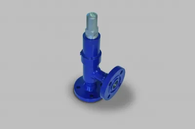
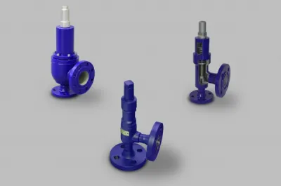
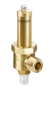
Safety valves are safety devices against excessive pressure. Since the safety valves in the delivery factory receive a TÜV approval, which is certified by an acceptance report, opening the valves or adjusting the spring force is not permitted.
Safety valves must always be installed in a vertical spindle position. They must be removed before the pressure test of the system, replaced with blind flanges and reinstalled only after completion of the test,
Safety valves with starter levers may no longer be used.
In the discharge line of each safety valve should be clearly visible and controllable an oil template with sight glass installed. It allows a continuous check for leaks (gas bubbles in the oil) and prevents condensation and rust on the spindle.
There must be no shut-off devices between the safety valve and the system part to be secured.
For containers that can not be emptied, we recommend using a shuttle valve combination with two safety valves (see Fig. 1). This figure also shows how it works.
This includes two representations, the simple arrangement of a shuttle valve and one in which the safety valve rupture discs are presented. This structure is used for special requirements in refrigeration technology. In this case, the safety valve is atmospherically completely relieved of pressure via an expansion valve unit and the primary effective safety device against impermissible overpressure in the system is the rupture disk. The safety valve will only take effect when the bursting disc breaks and the expansion valve unit closes. The rupture disc is something of a disposable product. It has the great advantage of being completely dense until it is released, and that is the appeal of its use. She has the night parts, to be destroyed when triggered and then no longer close and has about 10% a much greater release tolerance than the safety valve. Through the use of a shuttle valve combination, the system remains operational even when testing and repair of a safety valve through the second safety valve.
Fig. 1: Shuttle valve combination with safety valves
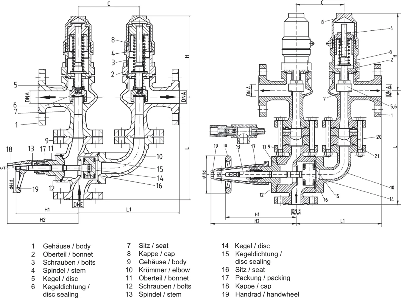
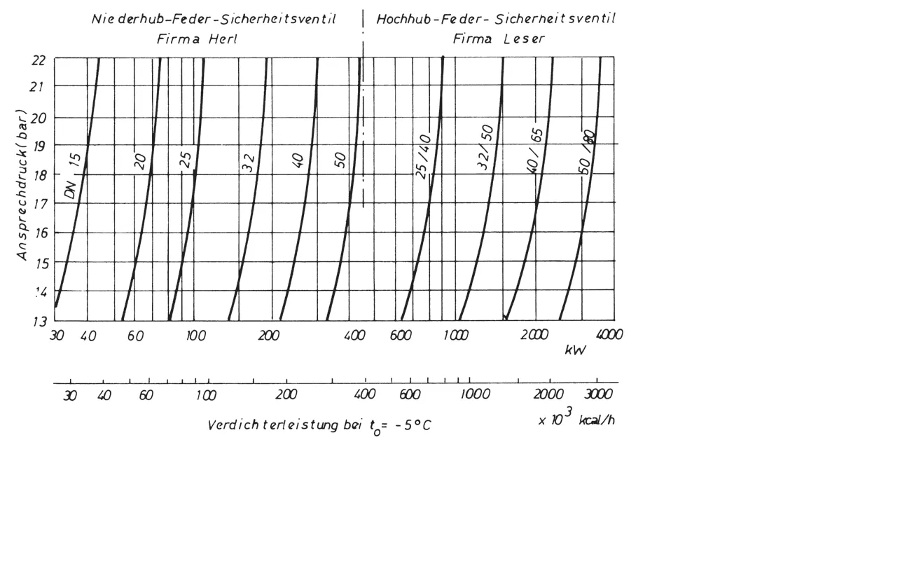
Fig. 2: Blow-off capacity of safety valves in NH3 refrigeration systems, expressed as the equivalent of the refrigeration capacity at separator operation to = -5 ° C

Source:
IKET (ed.)
Pohlmann Taschenbuch der Kältetechnik
Fundamentals, applications, worktables and regulations
21st, revised and expanded edition 2013
ISBN 978-3-8007-3393-4
VDE VERLAG GmbH, Berlin - Offenbach


