Explanation of the MSS line, Any MOP point, overheating, dimensioning of the liquid line, etc.
Components
11. April 2017
Electronic Expansion Valves (EEV) for refrigeration systems
Introduction
Optimum evaporator filling, even in the event of heavy load fluctuations, flexible MOP points and the highest possible evaporation temperatures to increase energy efficiency, are always an issue for plant engineers and operators in refrigeration technology. These requirements can often not be sufficiently taken into account with the usual thermostatic expansion valves. Electronic expansion valves, on the other hand, are ideal for this purpose.
Small overheating higher evaporation pressures better COP
The advantages of electronic overheating control are obvious. The evaporator is always optimally filled with refrigerant. Even with strong power fluctuations, so the most diverse partial load cases, the amount of refrigerant to be injected can be precisely metered. This is done by passing the current overheating in the evaporator via a pressure transmitter (marked "P" in Figure 1) and a very sensitive temperature sensor (Figure 1 "S2") to the controller "EKC 315A" in a timely manner.

The controller can now take measures to achieve optimally small overheating. This adaptive control of the refrigerant injection leads to an optimal use of the evaporator and thus to the highest possible evaporation pressures that can be realized in this specific system. This not only leads to higher COP values, but also to energy savings, because the COP value results from the quotient of cooling and drive power.
PERMANENT OPTIMIZATION OF OVERHEATING
The overheating always adapts to the minimum stable signal (MSS line) of the evaporator, so that the signal cannot drift into the unstable area (Figure 2 - left of the MSS line). The "EKC315A" controller first selects any desired overheating setpoint, eg 8 K. It then attempts to implement this 8 K as the setpoint in the system. Since all information, ie overheating temperature value "S2" and current evaporation pressure "P", come together here and, in addition, a history of these two values is saved to optimize the control function, the controller can easily decide whether the currently desired value is at the currently prevailing load conditions is feasible.
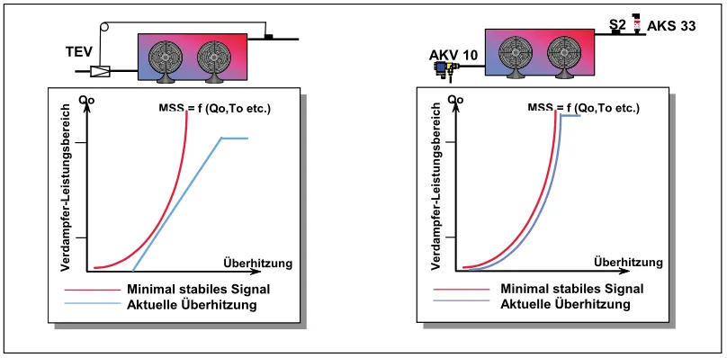
If, for example, the evaporating pressure fluctuates greatly and the superheat values change rapidly, this is a sign that a higher superheat setpoint should be aimed at. However, if superheat and evaporation pressure remain largely constant, you can continue with a lower superheat setpoint, eg 7 K (then 6 K, 5 K etc.). The permanent monitoring of the optimum superheat is a decisive advantage of electronic expansion control compared to purely thermostatic valves. These would have to be set in advance to the maximum overheating setpoint, which is described by the system's individual MSS characteristic curve. However, this value is not so easy to determine so that with a mechanical-thermostatic system, this already poor starting position is usually made worse by the fact that the fitter adds a "safety margin" to the required minimum overheating value during commissioning. With regard to the functional reliability of a system, this is not wrong, because a slightly higher overheating is certainly preferable to a temporary "shooting through". However, this measure has a negative impact on the energy situation in the plant. With the electronic "EKC 315A" injection system, this "safety margin" does not apply, since the system regulates itself with regard to overheating, as described. With regard to the functional reliability of a system, this is not wrong, because a slightly higher overheating is certainly preferable to a temporary "shooting through". However, this measure has a negative impact on the energy situation in the plant. With the electronic "EKC 315A" injection system, this "safety margin" does not apply, since the system regulates itself with regard to overheating, as described. With regard to the functional reliability of a system, this is not wrong, because a slightly higher overheating is certainly preferable to a temporary "shooting through". However, this measure has a negative impact on the energy situation in the plant. With the electronic "EKC 315A" injection system, this "safety margin" does not apply, since the system regulates itself with regard to overheating, as described.
ANY MOP POINT
An important point that is regularly neglected with electronic injection control is the free choice of the MOP point. As already described for the thermostatic expansion valves, the MOP point is the maximum evaporation pressure (“maximum operating pressure”) at which the expansion valve works. While there are basically only very specific MOP points for thermostatic expansion valves, for which a different component must be selected each time (e.g. -20 °C for deep-freeze applications or +15 °C as "climate MOP"), this point is electronic expansion valves can be freely selected and, if necessary, readjusted or completely modified. In most cases, the use of a start controller can be completely dispensed with, which equates to significant cost savings, especially in larger systems. At the same time, the desired setpoint can be set faster and more elegantly with the electronic variant than with a mechanical start controller.
Operation
The controller is operated using two pushbuttons. The controller can be completely programmed using these two buttons, combined with a three-digit display, with all important data being displayed. This means that every fitter on the system can intervene in the control loop or display relevant data. In the menu for the controller not only fundamentally adjustable values such as the type of refrigerant appear, but it is also possible to influence certain processes precisely by intervening in stability and amplification factors. This applies, for example, to the overheating control, so that overheating fluctuations can be prevented. You can also choose between adaptive and load-dependent overheating control. The adaptive superheat control has already been described in detail here. In the case of load-dependent overheating control, higher overheating is deliberately run in certain partial load cases, for example to ensure longer minimum compressor runtimes or to positively influence the frosting pattern on the evaporator. This could then be dispensed with one or the other defrost.
SERVICES
The service menu for the electronic overheating controller is particularly interesting for the fitter during commissioning and also when servicing the system. All parameter values that begin with "u" indicate actual system values that are used for all types of error diagnostics or are important for the evaluation of plant conditions. The three parameter values "display of overheating", "display of temperature at the S2 sensor" (meaning at the evaporator outlet) and "display of the evaporation temperature" must be observed in particular. These three values provide information about the system status. On the one hand, they can be read out quickly and do not have to be laboriously determined with the service pressure gauge and the fitter's temperature measuring device. On the other hand, you can see immediately which values the controller assumes as given. For example, it is part of the standard procedure for an experienced fitter to check all the sensors on electronic systems before they are actually put into operation (with the usual resistance sensors, this is quite easy to do with an ohm meter. For example, a P T1000 sensor has a resistance at 0 °C of 1000 ohms) to prevent lengthy troubleshooting if the actual values recorded by the sensor are incorrect. This procedure is no longer necessary when you look in the service menu, because you can assess directly (if in doubt, measure yourself with a thermometer or manometer) whether the value is realistic or not. in electronic systems, first checking all the sensors before actually putting them into operation (with the usual resistance sensors, this is quite easy to do with an ohm meter. For example, a P T1000 sensor has a resistance of 1000 ohms at 0 °C), to avoid lengthy troubleshooting prevent incorrectly recorded actual values by the sensor. This procedure is no longer necessary when you look in the service menu, because you can assess directly (if in doubt, measure yourself with a thermometer or manometer) whether the value is realistic or not. in electronic systems, first checking all the sensors before actually putting them into operation (with the usual resistance sensors, this is quite easy to do with an ohm meter. For example, a P T1000 sensor has a resistance of 1000 ohms at 0 °C), to avoid lengthy troubleshooting prevent incorrectly recorded actual values by the sensor. This procedure is no longer necessary when you look in the service menu, because you can assess directly (if in doubt, measure yourself with a thermometer or manometer) whether the value is realistic or not.
SWITCH OUTPUT RELAY MANUALLY
Of course, the outputs of the controller are just as important as the inputs. In order to simplify this particular point during commissioning, the controller menu offers the option of manually overriding the outputs for the "AKV" valve, the solenoid valve and the alarm output. Typical for control problems is the question of whether the controller does not switch the output because it does not consider it necessary for some reason, or because it cannot switch the output, for example due to a defect. This point has cost even experienced fitters hours and days of troubleshooting. For this reason, it is advisable to try out the corresponding output relays individually during commissioning. In this way, wiring and assignment errors are also quickly cleared up.
STEADY ELECTRONIC VALVES
In principle, it is possible to work with an "ETS", "ICM" or an "AKV" valve. These actuators differ as follows:
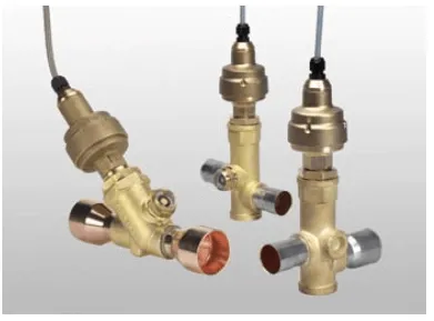
The "ETS" and "ICM" device is a continuous valve that is often used in chillers with the refrigerant R407C, for example, when every degree of overheating counts and even the slightest fluctuations in the evaporation pressure are to be avoided. The controller can be used as a P, PI or PID controller. The P control is a standard control according to the deviation (example: if the superheat becomes too large, the opening degree of the valve is always increased at the same speed). With PI control, the "reset time" ("I component") can be changed separately. That is, the reaction speed of the control can be changed, in other words, the control becomes more nervous or sluggish. Both may be required. The "D component" in PID control also optimizes the control properties in the event of a sudden setpoint change. This control mode is particularly advisable if the injection system is operated with an external overheating setpoint shift, eg from a higher-level controller. When using an "ETS" or "ICM" valve, a solenoid valve should also be provided in the liquid line, which can also be controlled by the "EKC". If the solenoid valve really has to be dispensed with, then it is essential to connect a UPS (independent power supply) to the actuator ("ICM") or to the controller ("ETS"). This is absolutely necessary since an "ICM" or "ETS" remains in its current open position in the event of a sudden power failure and thus continues to inject refrigerant into the evaporator, which can lead to greater damage up to and including compressor failure. With a UPS, the valve can still be closed even in such a case.
PULSE WIDTH MODULATION
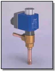
With pulse width modulation and the use of an "AKV" valve, there is no need for an additional solenoid valve in the liquid line, as this can permanently close the flow of the liquid line and automatically return to the closed position in the event of a power failure.
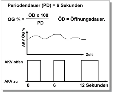
The "EKC-AKV" combination works on the principle of pulse width modulation. This means that the "AKV" valve is fully opened for a certain time and fully closed again for the rest of the period time, depending on the degree of opening of the valve. For example, with an opening degree of 50% and the standard period of 6 s (this variable can be changed), this would mean 3 seconds open and 3 seconds closed (at 20% opening degree, corresponding to 1.2 s open and 4.8 s closed).
DIMENSIONING OF THE LIQUID LINE
Especially when using pulse width modulated valves, the dimensioning of the liquid line should be given high priority. In general, a speed of 0.5 m/s is given as a guide value in the relevant specialist literature when designing the diameter of the liquid line. However, if you look at existing refrigeration systems, this value is closer to approx. 1 m/s. Since this is not usually a problem for normal (continuous) thermostatic expansion valves, this guideline value has become widely accepted. With pulse-width modulated valves, however, the situation is different. Here you should even go as far as designing the 0.5 m/s for the maximum valve performance and not just for the evaporator performance. Most plant builders would probably design a 12 mm copper pipe as the liquid line for a 7 kW evaporator with R404A and -10 °C evaporation (without special subcooling). At 0.92 m/s, the flow rate would be well within the usual range. With "strictly 0.5 m/s", however, a 15 mm or 16 mm pipe with approx. 0.5 m/s would then be required. Finally, if the valve capacity is taken into account instead of the evaporator capacity, an 18 mm pipe could even be necessary (example: valve capacity 10 kW. "AKV" valves are never designed for 100% opening - opening degrees between 30 and 70% should be aimed for) . If you take this principle into account, there are usually no accelerated liquids in the system, which can otherwise lead to roaring noises and vibrating pipelines.
HUMIDITY
Refrigeration experts know that the subject of "moisture" plays an important role in refrigeration technology and particularly in the case of unpackaged goods, meat, vegetables and fruit. Nevertheless, this topic is not tackled as aggressively here as in comfort air conditioning technology, in which appropriate hygrostats and especially steam humidifiers are used across the board if the humidity is too low. Nevertheless, depending on the situation, it may also be necessary to dehumidify in refrigeration systems. Indirect measures are usually used for this purpose, e.g. B. changing the evaporator fan levels or the evaporator speed. (ie slower fan speed = lower evaporating temperature = dehumidification and vice versa). With an electronic injection system, this point can be influenced directly: Simply shift the superheat setpoint with an external signal of 4-20 mA and no or hardly any dehumidification is achieved with the smallest possible superheat values or high dehumidification with high superheat values. Of course, it also applies here that the dew point must always be undershot for dehumidification. The adjustment of such a system can always be carried out quite easily due to the amount of condensate that is separated out on the evaporator. In addition to storing vegetables and fruit, such a system is also suitable for comfort air conditioning HVAC systems and climate cabinets. that the dew point must always be undercut for dehumidification. The adjustment of such a system can always be carried out quite easily due to the amount of condensate that is separated out on the evaporator. In addition to storing vegetables and fruit, such a system is also suitable for comfort air conditioning HVAC systems and climate cabinets. that the dew point must always be undercut for dehumidification. The adjustment of such a system can always be carried out quite easily due to the amount of condensate that is separated out on the evaporator. In addition to storing vegetables and fruit, such a system is also suitable for comfort air conditioning HVAC systems and climate cabinets.
Stephan Bachmann,
Danfoss Kältetechnik, Offenbach
Contents
Product Ad
Image

AKV are electrical expansion valves with a solenoid valve function
Jobs
Fitter refrigeration technology
MTA Refrigeration Technician (m/f/d) in Customer Service for Baden-Württemberg
To strengthen our team for the Stuttgart region, we are looking for you as a Refrigeration Technician (m/f/d) for our customer service.
Image
MTA Deutschland GmbH
Nettetal, Germany
Fulltime
Mounting
Mechanic/Welder (m/f/d) at GEA
We are looking for three mechanics/welders (m/f/d) at our Berlin location.
Image
GEA Refrigeration Germany GmbH
Berlin, Germany
Fulltime
Project management refrigeration technology
Commercial Employee Order Processing in Engineering (m/f/d)
To strengthen our team, we are looking for a commercial employee to handle engineering projects as soon as possible.
Image
MTA Deutschland GmbH
Nettetal, Germany
Related Products
Image

The SER, SERI and SEHI are Electronically Operated Step Motor flow control valves, intended for the precise control of liquid refrigerant flow.
Image

The CEV step motor expansion valve provides precise flow control for virtually every refrigeration, air- conditioning, and heat pump application
Image

The Parker Valve Station (PVS) is an integrated design featuring proven solenoid, regulator or electronic valve modules in conjunction with isolation valves, check valve and strainer.
Image

ETS is a series of electrically operated expansion valves
Image

The multifunctional valve station ICF offers savings in assembly times, purchasing and space requirements.