*c-Ejektor is used to increase efficiency in CO 2 boosters.
Components
11. June 2018
The CO2 ejector
Ejectors are used to increase efficiency in CO2 booster systems.
The ejector
*c-Ejector is used to increase efficiency in CO2 booster systems. In conjunction with a high-pressure valve, three different types of gas injectors and two types of liquid ejectors can be combined as required.
![]()
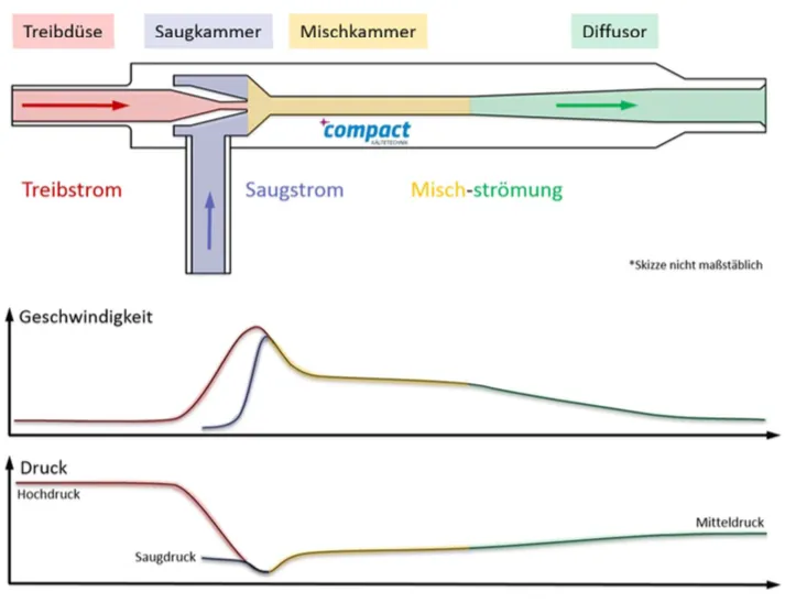
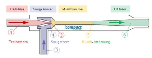
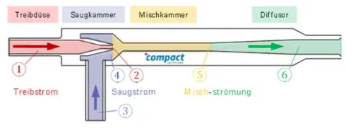
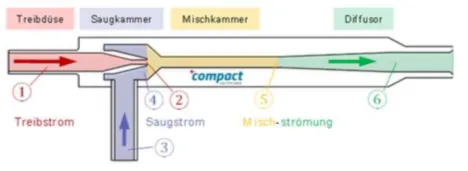
Principle mode of action of an ejector
The *c-Ejector utilizes the expansion work existing in the refrigerant at the gas cooler exit to draw in a different partial mass flow and to promote a higher pressure level. The exiting at high pressure level from the gas cooler CO2 is accelerated in the motive nozzle. As a result, the static pressure decreases and the flow exiting the motive nozzle has a lower pressure than the suction pressure of the NK stage. This allows either gas or liquid to be withdrawn from the suction side of the NK compressors. Both partial streams mix in the mixing chamber. In the diffuser, the flow is decelerated again, causing a pressure increase to medium pressure level. After the diffuser, the mixture is passed into the medium pressure separator.
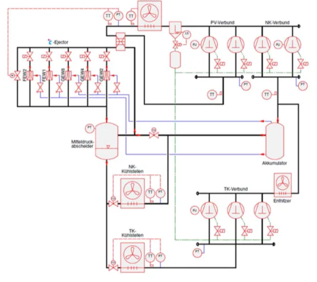
Integration of the *c-Ejector into a booster system
The starting point for integrating the *c-Ejector into an R744 refrigeration system is a booster system with parallel compaction. The flash gas accumulating in the medium-pressure separator is sucked off by a parallel compressor, thus keeping the pressure in the medium-pressure separator constant. In addition, gas ejectors can be installed, which suck the gas vaporized after the NK-cooling points before the NK-compressors and promote it to a higher pressure back into the medium-pressure separator.
If an accumulator is added after the NK cooling points, the cooling points can be operated quasi-flooded. The accumulating in the accumulator liquid is sucked from the liquid ejectors and conveyed back into the medium pressure.
Functioning of gas and liquid ejectors
There is a general distinction between two types of ejectors: gas and liquid ejectors. But what exactly is the difference between gas and liquid ejectors? Let's look first at the gas ejector in the log ph diagram:
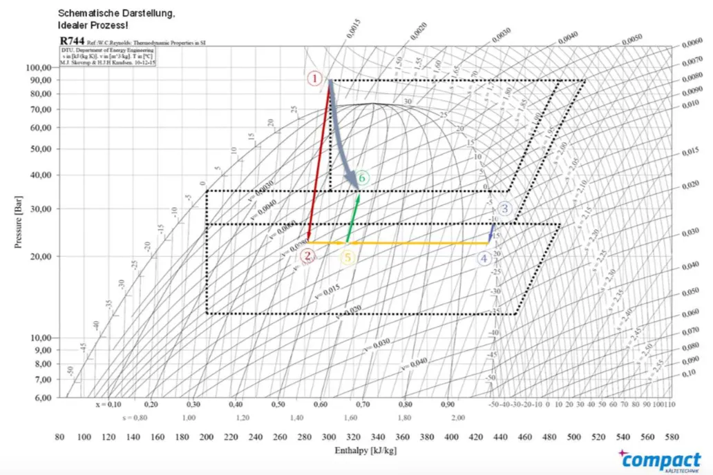
The motive flow is relaxed from 1 to 2 in the motive nozzle below the NK pressure level. Saturated gas can be sucked from 3 to 4. Depending on the entrainment ratio, point 5 sets at the end of the mixing chamber. In the diffuser, the mixture is recompressed from 5 to 6 again. The line of action of the gas ejector thus has a higher vapor content in the medium-pressure separator.
Of the NK compressors, the gas ejector extracts a refrigerant mass flow and promotes this in the medium pressure. From this, the parallel compressor sucks off the accumulating gas. The efficiency advantage lies in the fact that the parallel compressor must apply a lower pressure difference to the high pressure than the NK compressor and this is thus relieved.
The prerequisite for the effective use of the liquid ejector is the quasi-flooded operating mode of the cooling points. The liquid ejector acts like a refrigerant pump. It conveys liquid refrigerant directly from the suction-side accumulator of the normal cooling stage into the medium-pressure vessel. The accumulator is a container which is installed in front of the NK compressors and separates the liquid from the gas phase. The mass flow drawn in by the ejector can again be fed directly to the cooling points. Furthermore, a conventional injection valve can be used at the cooling points, which is regulated after a very slight overheating below the MSS. An increased heat transfer coefficient causes the same heat transfer surface a lower possible temperature difference between the refrigerant and the refrigerant. As a result, the evaporation temperature can be raised. The NK compressors only have to apply a lower pressure difference to the high pressure.

The motive flow is relaxed from 1 to 2 in the motive nozzle below the NK pressure level. Saturated liquid can be sucked from 3 to 4. Depending on the entrainment ratio, point 5 sets at the end of the mixing chamber. In the diffuser, the mixture is recompressed from 5 to 6 again. The line of action of the liquid ejector thus has a lower vapor content in the medium-pressure separator.
With the aid of the liquid ejector, the accumulating liquid can be pumped back to medium pressure "for free". The greatest efficiency gain is achieved when both types of ejectors are combined.
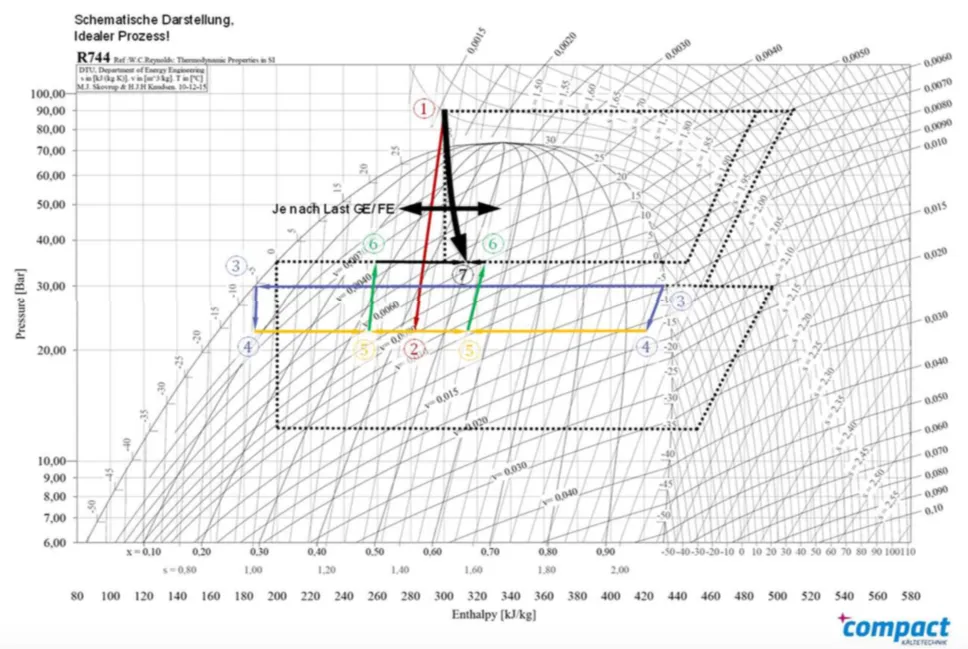
Gas and liquid ejectors suck saturated or saturated liquid from the accumulator. Depending on the load ratio of gas to liquid ejectors, a point 7 sets after mixing the two partial streams, which indicates the entry into the medium-pressure separator.
Efficiency gain with *c-Ejector
Even a booster with flash gas bypass can be operated more efficiently than a conventional two-stage refrigeration system (eg cascade with R134a / R744, satellite network with R404A) at low outside temperatures (<10 ... 15 ° C, depending on the design). Due to the transcritical operation of the booster but has to accept significant losses at high outside temperatures. To counter this, the installation of a parallel compressor is recommended. This ensures that the accumulated in the summer high proportion of flash gas in the collector no longer needs to be sucked through the NK compressor. Depending on the configuration of the parallel compressor, there is a switch-off point under which flash gas bypass mode must be switched again. Nevertheless, savings of well over 10% can be expected on a few days a year.
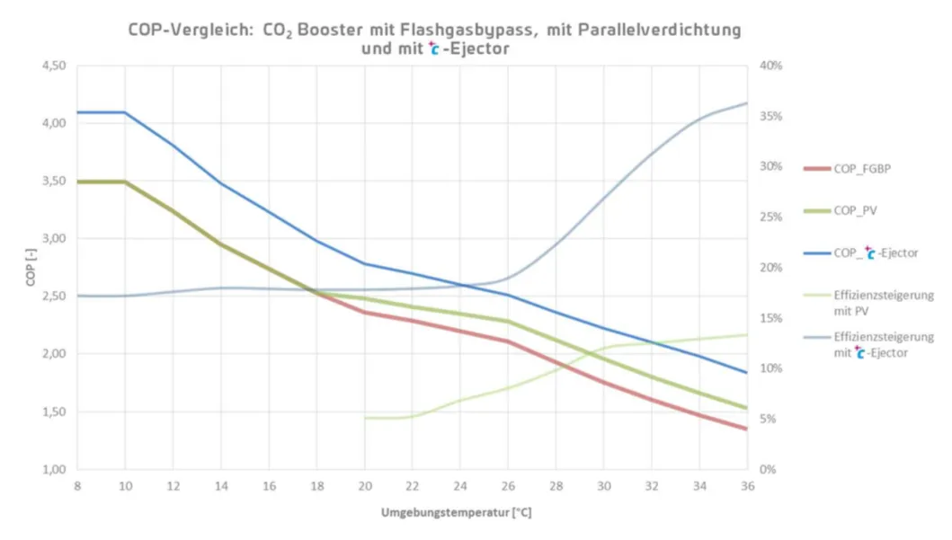
With the installation of *c-Ejectors, the cooling system can be operated more efficiently throughout the year if the overall system is designed correctly. Due to the gas ejectors, even in subcritical operation, sufficient flash gas accumulates in the medium-pressure separator, which prolongs the running time of the parallel compressor. At high outside temperatures, the efficiency gains are significantly higher than those of parallel compaction due to the design of the ejectors on a typical summer day.
Contents
Product Ad
Image

*c-Ejector is used to increase efficiency in CO2 booster systems.
Jobs
Fitter refrigeration technology
MTA Refrigeration Technician (m/f/d) in Customer Service for Baden-Württemberg
To strengthen our team for the Stuttgart region, we are looking for you as a Refrigeration Technician (m/f/d) for our customer service.
Image
MTA Deutschland GmbH
Nettetal, Germany
Fulltime
Mounting
Mechanic/Welder (m/f/d) at GEA
We are looking for three mechanics/welders (m/f/d) at our Berlin location.
Image
GEA Refrigeration Germany GmbH
Berlin, Germany
Fulltime
Project management refrigeration technology
Commercial Employee Order Processing in Engineering (m/f/d)
To strengthen our team, we are looking for a commercial employee to handle engineering projects as soon as possible.
Image
MTA Deutschland GmbH
Nettetal, Germany
Related Products
Image

transcritical CO2 plants and optimized refrigeration with the CO2 Booster series *carbo-Rack.